Arduino Serial in adaptor:ex
In this tutorial you will learn how to send commands from adaptor:ex to your Arduino mikrocontroller (Blink LED and Fade LED) and how to receive and react to data from your mikrocontroller in adaptor:ex (Push Button and Turn Knob).
There are several ways to integrate mikrocontrollers like those from Arduino into your game. In this tutorial we will use the serial port on your computer. To do this, you need to have adaptor installed on a device with a USB port - i.e. a laptop, PC, Raspberry Pi or similar. - installed. How to do that is described here: adaptor:ex install
You also need:
- a mikrocontroller that you can program via the Arduino IDE
- an LED
- a resistor ~ 200 Ohm
- a resistor ~ 10k Ohm
- a push button
- an adjustable resistor (potentiometer)
Blink LED
Let's stick to tradition and start by making a single LED light up via adaptor:ex and our mikrocontroller.
In our example, we use the legendary Arduino UNO. However, for many other mikrocontrollers that can be programmed via the Arduino IDE, you can follow exactly the same steps.
The Arduino setup
Before we create a device in adaptor:ex and create a new level, we set up our Arduino LED circuit and play a simple sketch on the Arduino.
You've probably already connected an LED to your Arduino and played the "Blink" example sketch.
Follow the setup in this Arduino Basics example or use the onboard LED of the Arduino UNO.
Add a serial query to the example sketch and query the incoming string for "led_on" and "led_off":
// the setup function runs once when you press reset or power the board
void setup() {
  // initialize digital pin 13 as an output.
  pinMode(13, OUTPUT);
  Serial.begin(115200);
  Serial.println("Hello Adaptor!");
}

// the loop function runs over and over again forever
void loop() {

  if (Serial.available()) {
    String incoming = Serial.readStringUntil('\n');

    if(incoming == "led_on"){
      digitalWrite(13, HIGH);   // turn the LED on (HIGH is the voltage level)
      Serial.println("Led is ON");
    }
    if(incoming == "led_off"){
      digitalWrite(13, LOW);    // turn the LED off by making the voltage LOW
      Serial.println("Led is OFF");
    }
  }
}
Create an adaptor:ex device
First create a new game in adaptor:ex, or open one that you have already created.
Then set up a new serial device in your adaptor:ex game under 'Game > Settings'.
If you have not already done so, add the Devices Plugin to your game.
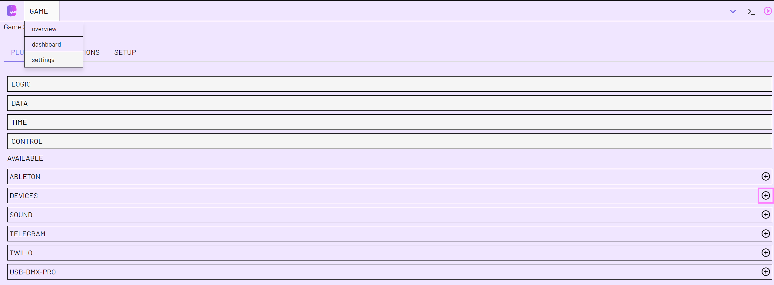
and then create a new Serial Device.
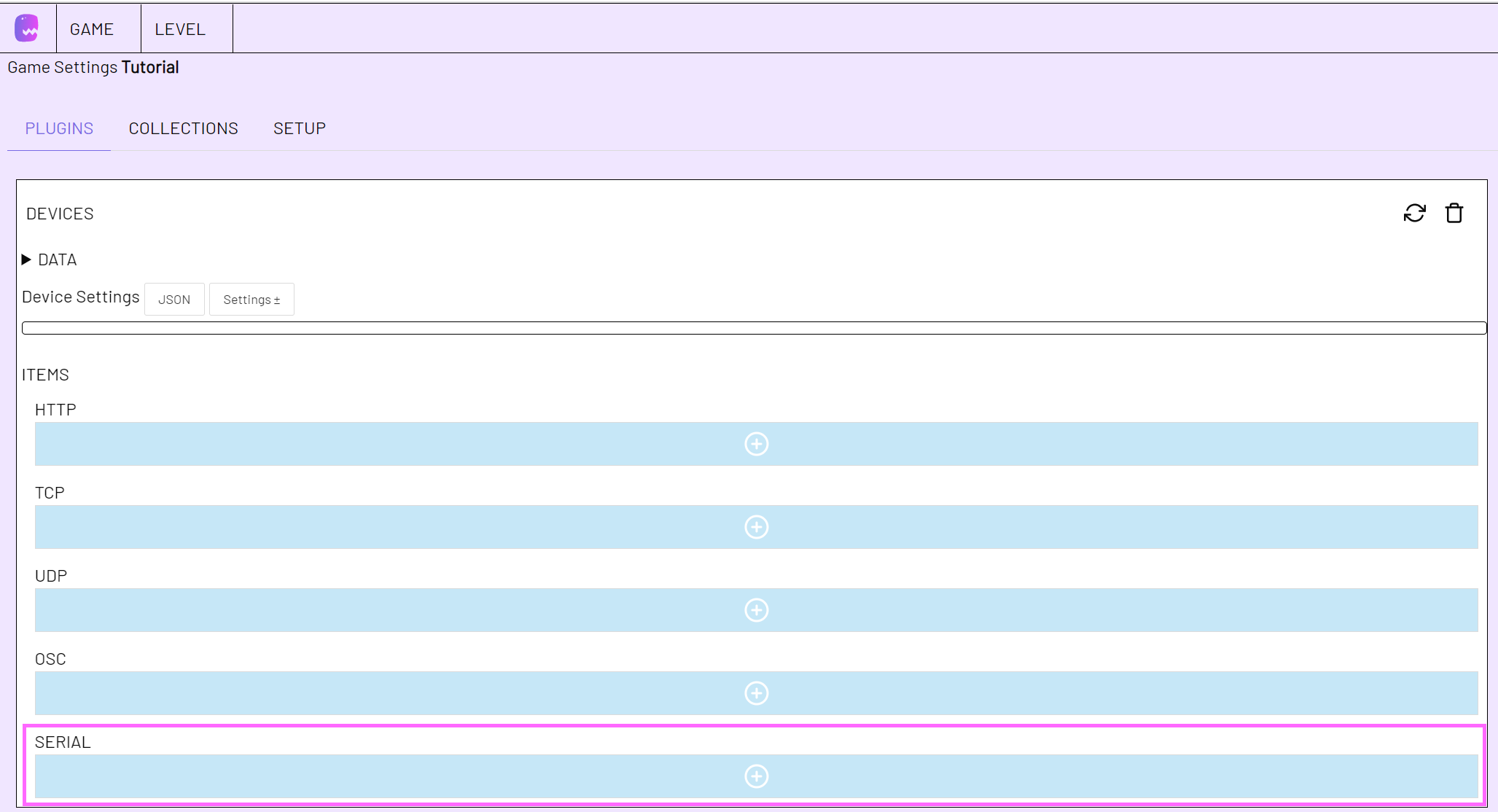
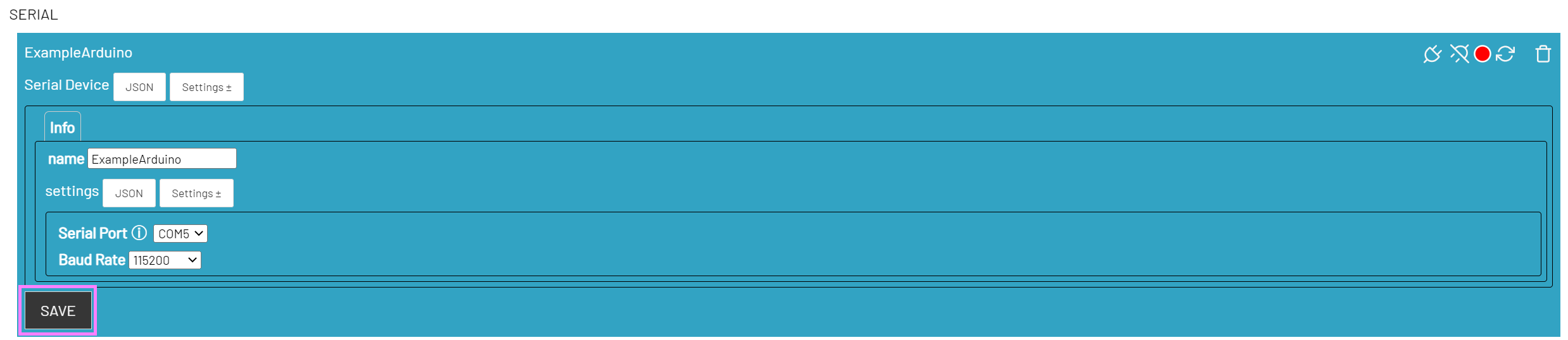
Give the device a suitable name (name). Here we call it "ExampleArduino".
If your Arduino is connected to the computer, you should now be able to select the Serial Port under settings. If you have unplugged the Arduino in the meantime, use the reload button of the Devices plugin to make adaptor:ex look for new devices.

Set the baud rate to the same one you use in the Arduino Sketch. In our example the baud rate is set to 115200.
Click on SAVE to create the serial device.
Note
To record your Arduino, the Arduino IDE uses the same serial port as adaptor:ex. If you modify the sketch and update your Arduino, remember to disconnect your device in adaptor:ex first. Reconnect the device after the upload to use it in adaptor:ex.

The Send Message Action
Create a new level in Game > overview by clicking on Add new and give it a name of your choice.
Search for the action Send Message under DEVICES in the left sidebar, the Toolbar. Drag the action to the Stage.
Drag the Send Message action from the toolbar to the stage A new State is created. Click on the Send Message Action to edit it.
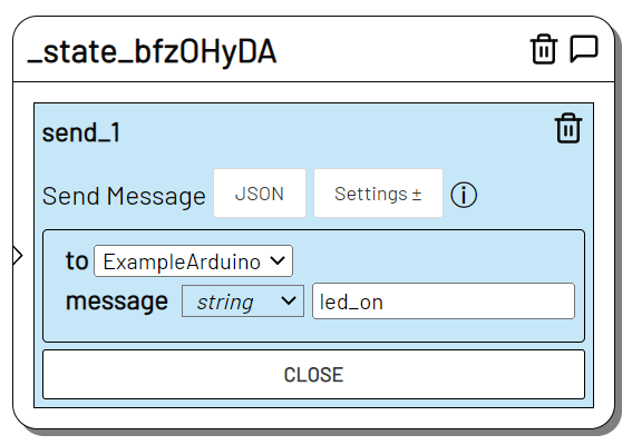
Since we have only created one device so far, our Serial Device is already selected under 'to'.
Open the Settings menu and select message.
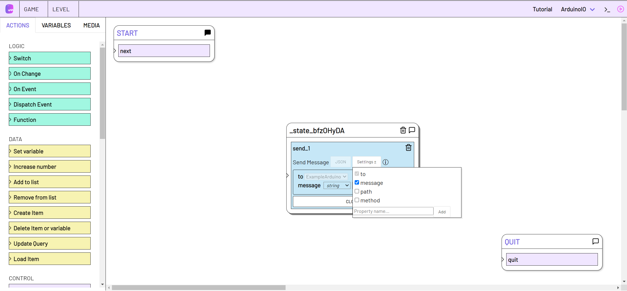
With message we define what will be sent to the Arduino. In the Arduino sketch, we specified that the LED should be turned on when the serial port receives led_on. So this is the text we need to specify at this point
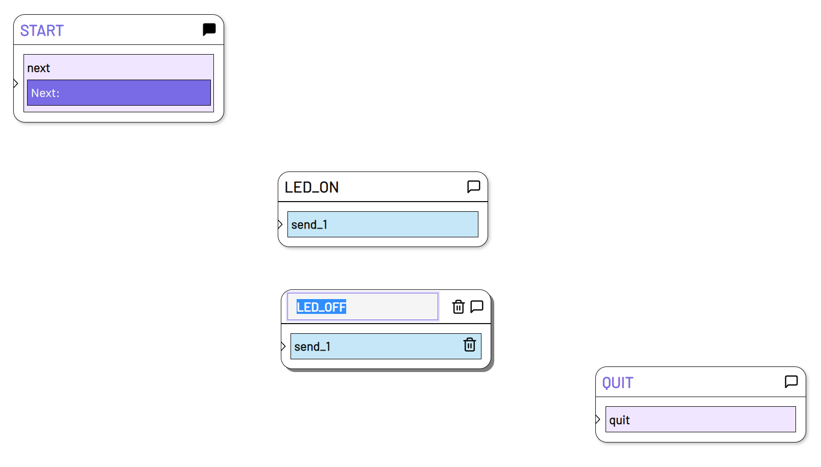
Then we directly create a second state with a Send Message Action, in which we enter the message "led_off".
So that you know in which state what will happen, rename the states by double-clicking the name at the top of the state.
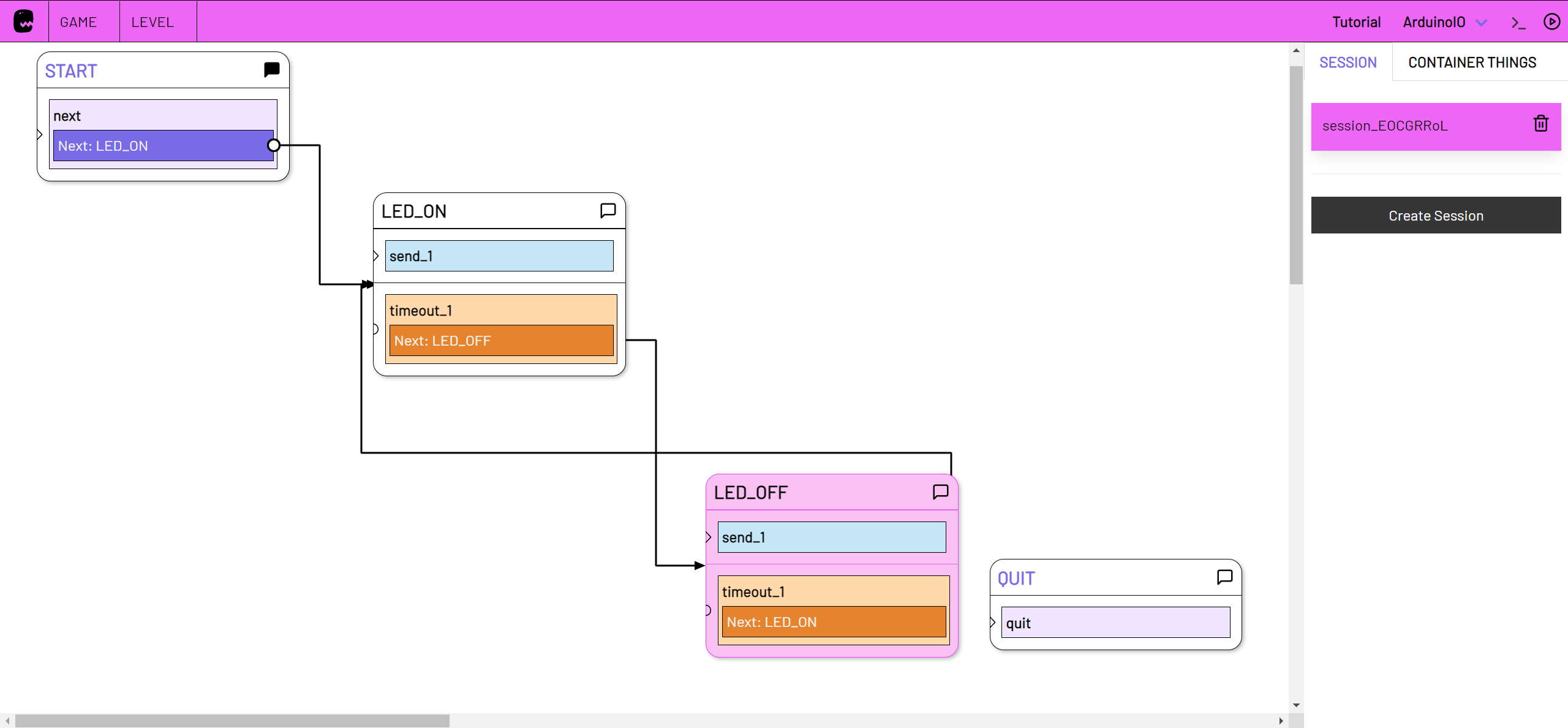
We have set up our level wit enough to test it. Let's see how we can send the newly created messages.
Send messages
To send the messages to the Arduino, we need to start a live instance of our level. To do this, switch to Live Mode by clicking on the triangular button in the top right corner of adaptor:ex.
Switch to live mode](./assets/adaptor_live.png)
A new menu opens in the right sidebar. Create a new live session with 'Create Session' and then click on 'Start Session'.

Click on the "LED_ON" state to send "led_on", or on the "LED_OFF" state to send "led_off" to your Arduino.
If everything is set up correctly, the LED on your mikrocontroller should light up or go off accordingly.
Troubleshooting
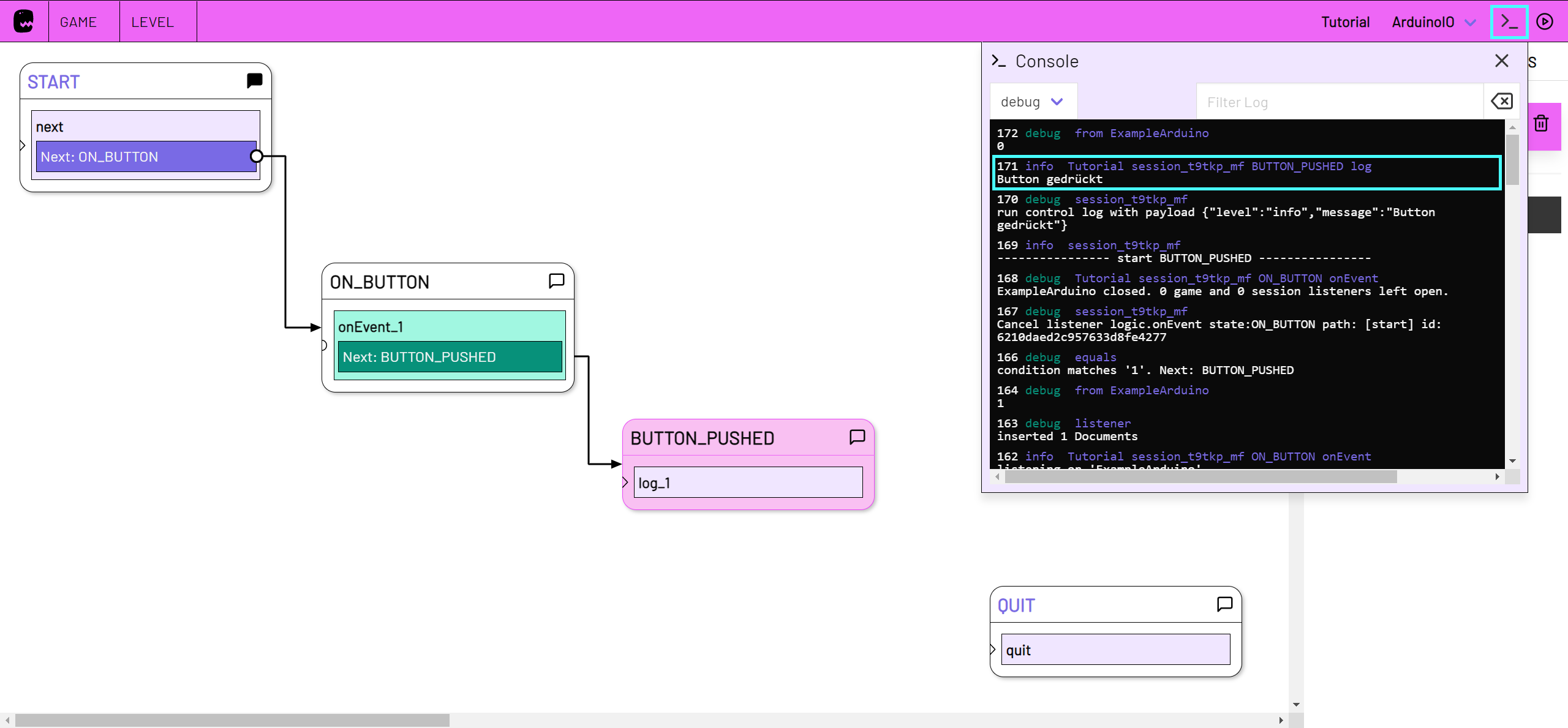
Take a look at the console to see what is happening and whether any error messages are appearing.
You can find the console in the adaptor:ex editor in the top right corner, to the left of the Live Mode button.
Open the log console](./assets/adaptor_console.png)
In the console you can also observe when the Arduino sends a message to adaptor:ex. For example, if you disconnect and reconnect the device, you should be able to read in the console the message "Hello Adaptor!" that your Arduino sends in setup().
If necessary, add more Serial.println() to your Arduino sketch to find out what the Arduino is sending.
Remember that if you want to use the Serial Monitor of the Arduino IDE to see what the Arduino is sending, you have to disconnect the device in adaptor:ex under
Game > settings > Devices > Serialfirst.
Blink with timeouts
Switch back to the level editor mode by clicking on the triangle icon in the top right corner again.
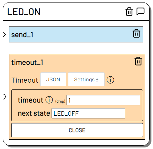
To make the LED blink without our intervention, we add a Timeout action to our existing states. You can find it in the toolbar under 'TIME'.
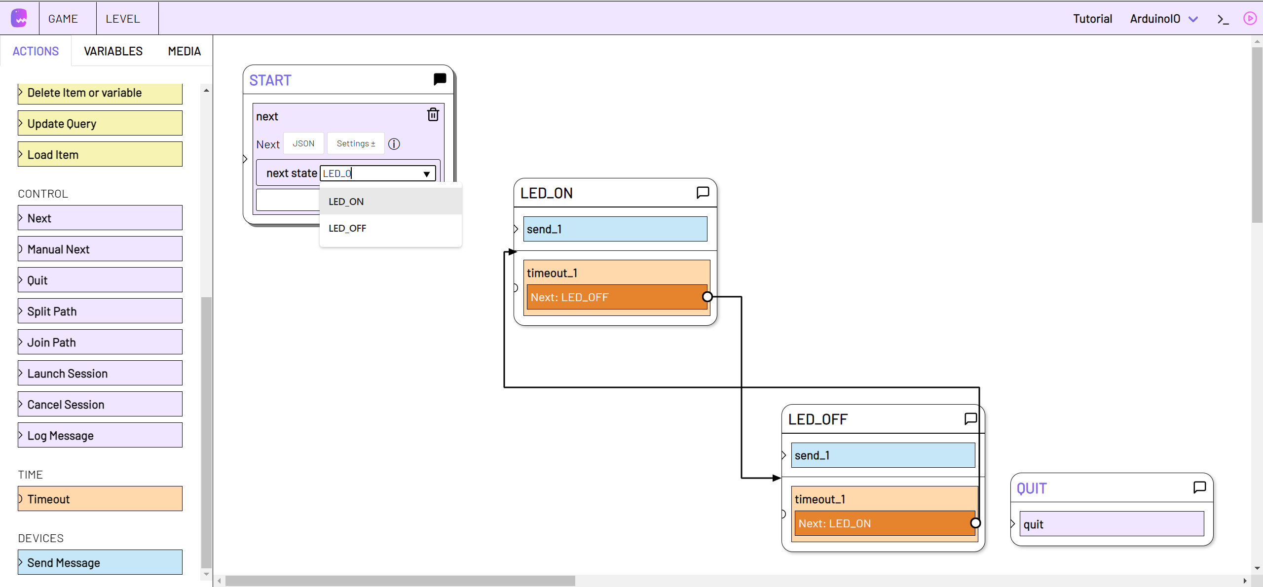
Drag the timeout action from the toolbar to the "LED_ON" state. You can edit it by clicking on it. Enter the number of seconds under 'timeout' and select your 'LED_OFF' state under 'next state'.
Add another timeout to the "LED_OFF" state. This time select "LED_ON" as the next state.
You can also specify fractions of seconds for the timeout using dot notation. E.g.
0.5for 500 milliseconds.
For the sake of completeness, we now connect "LED_ON" to the "START" state so that our level starts immediately when we create a session. Open the Next in "START" and select "LED_ON" as next state.
Switch to live mode and close your last created session if necessary.
As soon as you create a new session, your LED should start flashing.
Fade LED
Dimming a light-emitting diode is also one of the basics of the Arduino examples: Fading a LED
As in the chapter Blink LED, we also have to supplement the Arduino sketch here with a serial query.
int led = 9;           // the PWM pin the LED is attached to

// the setup routine runs once when you press reset:
void setup() {
  // declare pin 9 to be an output:
  pinMode(led, OUTPUT);
  Serial.begin(115200);
  Serial.println("Hello Adaptor!");
}

// the loop routine runs over and over again forever:
void loop() {
  // set the brightness of pin 9:
  if (Serial.available()) {
    analogWrite(led, Serial.parseInt());
  }
}
Create a new level in 'Game > overview' and open the editor, or continue working in the existing level.
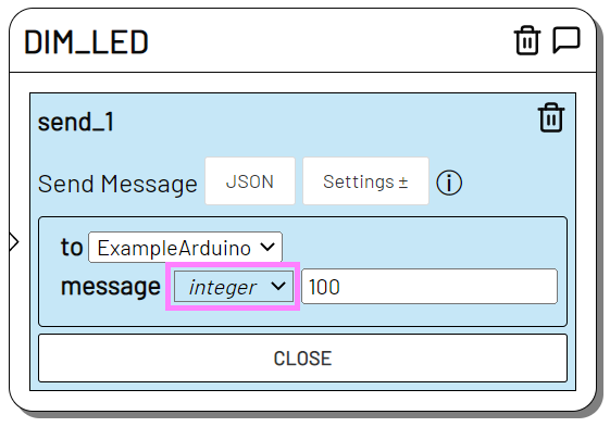
Instead of a text message, we now send a numerical value between 0 and 255 to the Arduino with the Send Message action. Drag the Send Message Action onto the stage to edit it.
Select message in Settings. Change the data type from string to integer (i.e. to an integer value) and enter a value between 0 and 255.
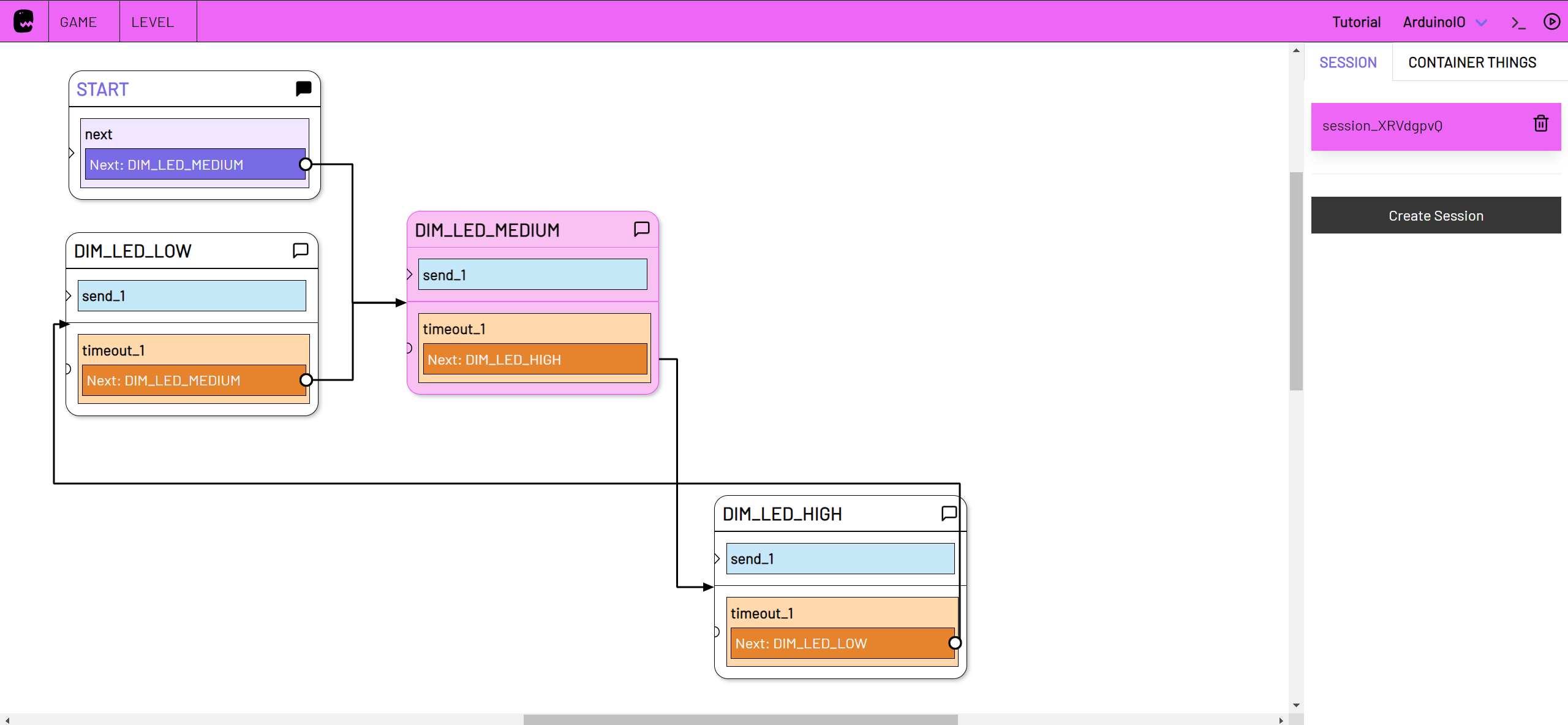
Add more states with Send Message action that send a numerical value to your Arduino device. Connect the states with Timeout actions.
Switch to live mode and create a new session. The LED on pin 9 of your Arduino should now light up with varying intensity.
Push Button
We have already received messages from your Arduino in adaptor:ex, but have not yet been able to do anything with them. We should change that.
Arduino Sketch
Here's another Arduino starter example that we can use to good effect to send messages from the Arduino to adaptor:ex: Digital Read Serial
Follow the setup, connect a button to your mikrocontroller.
We make a few small changes to the sketch before we start in adaptor:ex. The baud rate of the serial port has to be adapted to our device. We also want the Arduino to only send a message when something actually changes. Therefore we add a status variable.
Here is the adapted sketch:
// digital pin 2 has a pushbutton attached to it. Give it a name:
int pushButton = 2;
int buttonState = 0;

// the setup routine runs once when you press reset:
void setup() {
  // initialize serial communication at 9600 bits per second:
  Serial.begin(115200);
  // make the pushbutton's pin an input:
  pinMode(pushButton, INPUT);
}

// the loop routine runs over and over again forever:
void loop() {
  // read the input pin:
  int buttonValue = digitalRead(pushButton);
  // print out the state of the button if it changed:
  if(buttonValue != buttonState) {
     Serial.println(buttonValue);
     buttonState = buttonValue;
  }
}
The On Device Message Action
Open the adaptor:ex level you used in the previous chapter to switch an LED on and off.
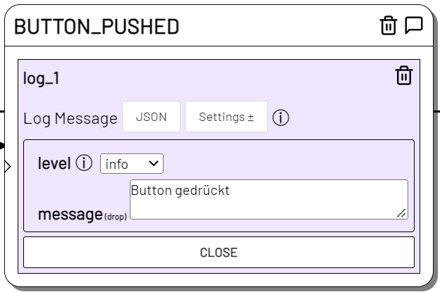
First create a new state that we want to trigger when the button on our Arduino is pressed. The Log Message action is suitable for this. You can find it in the Actions Toolbar under 'CONTROL'.
Drag the log message action onto the stage and rename the new state "BUTTON_PUSHED".
Edit the Log Message Action. Write "Button pushed" in message.
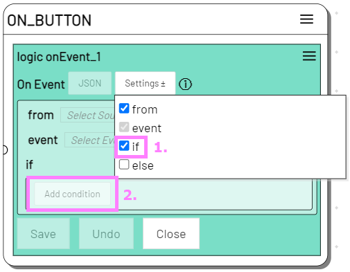
To react to messages sent by a device, we use the On Device Message action. You can find it, just like the Send Message action, in the Level Editor in the toolbar under 'DEVICES'.
Drag the On Device Message Action to an empty place on the stage and open it to edit it.
Select your device from the device dropdown.
Add the if Settings option and create a condition with Add condition.
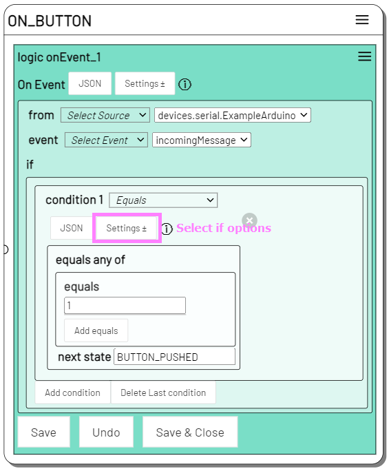
We have only this one button, but we have to distinguish if the button is pressed or released. So let's directly query what exactly our Arduino is sending.
field can be ignored for now, as we are only receiving simple text messages.
In equals we put 1, because we expect the Arduino to send 1 (or true, which is the same in this case) when the button is pressed.
As next state we select our "BUTTON_PUSHED" state.
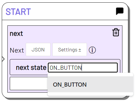
As a last step in the editor we connect the "START" state with "ON_BUTTON". Open the next action in the "START" state and select "ON_BUTTON" as next_state.
Switch to live mode and create a new session. The "START" state has passed directly to "ON_BUTTON".
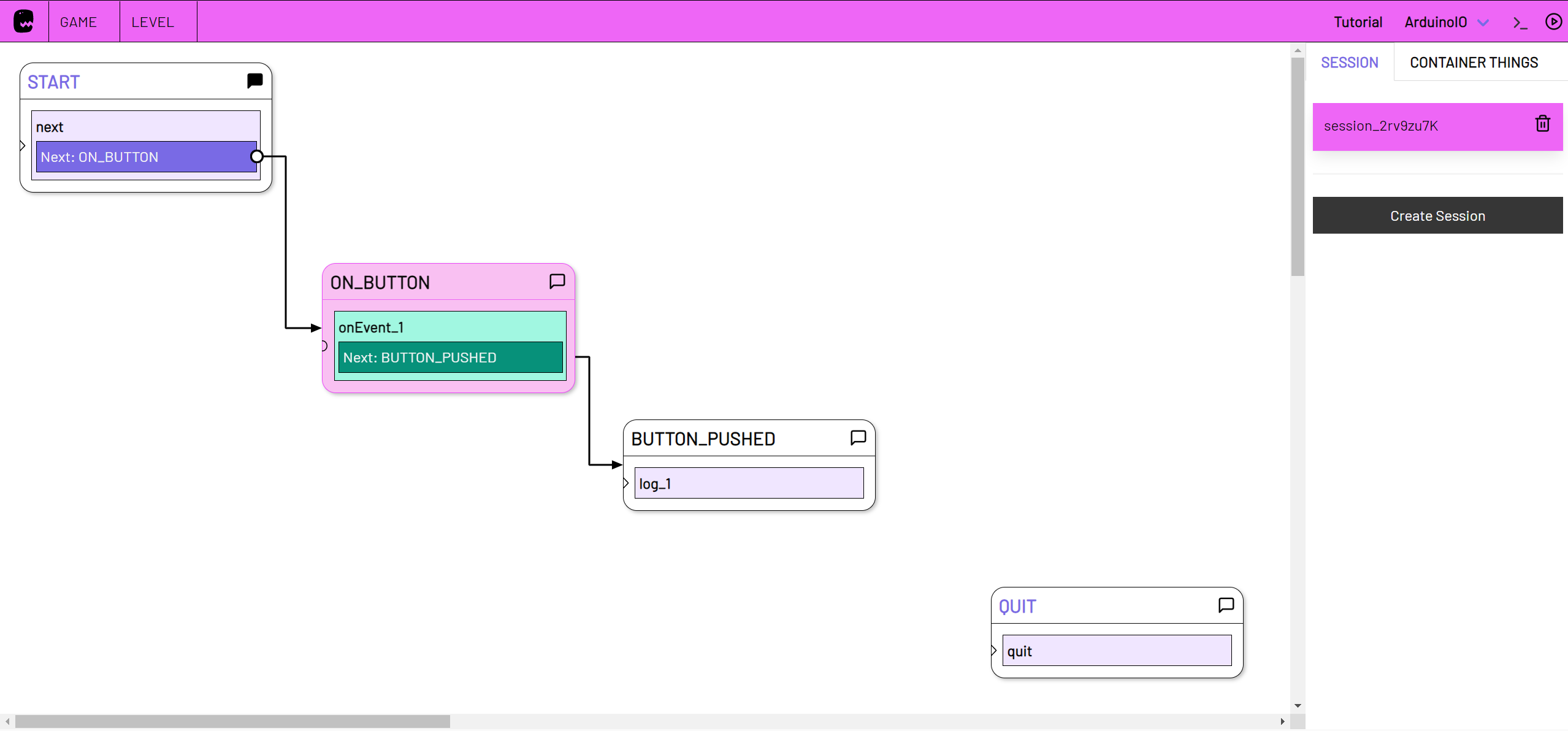
When you push the button in your Arduino setup, the session should change to the "BUTTON_PUSHED" state.
Open the Log Console by clicking on the arrow button in the top right corner of the title bar. Your log message should be displayed there.
To repeat the process click the trigger button for "ON_BUTTON". The On Device Message listener is started again and triggers the next state as soon as the button is pressed.
Turn Knob
You can also use the On Device Message action to react to analogue inputs.
Connect an adjustable resistor - e.g. a potentiometer or light-sensitive resistor - to your Arduino.
Here is the example in the Arduino documentation: AnalogReadSerial
Again, we need to change the baud rate of the serial port to 115200:
// the setup routine runs once when you press reset:
void setup() {
  // initialize serial communication at 115200 bits per second:
  Serial.begin(115200);
}
In adaptor:ex you now create a state with the name "HIGH", which we want to trigger when the analogue input surpasses a high value.
Drag a new On Device Message Action onto the stage and edit it. Select your device and add a new condition.
To switch to the next state when one of the incoming analogue messages exceeds a certain value, select the Greater Than condition.
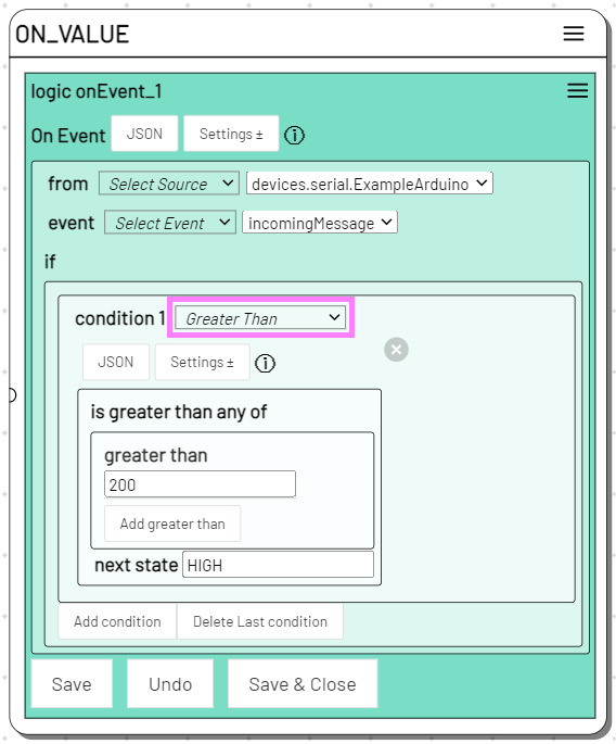
Activate the "ON_VALUE" state in live mode in your session. If the incoming value from the Arduino exceeds 200, the session switches to the "HIGH" state.
Address messages
If our mikrocontroller is equipped with several sensors, LEDs, servos, etc., we need a way to assign the messages we send.
In Send Message as well as in On Device Message and the other Logic Actions we can use Javascript Object Notation (JSON). JSON is a common form of notation for arranging and addressing data.
For the Arduino IDE, it is recommended to use the ArduinoJSON library to interpret and create JSON data.
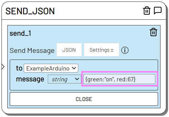
Send a JSON formatted message, e.g. {green: "on",red:67},
and respond to incoming messages in adaptor:ex that have JSON as content.

Specify in field the value within the received JSON you want to check, here knob.
Info
You can also read more deeply nested JSON values by addressing them using dot notation (deeper.nested.value).
Here is an extended Arduino sketch with ArduinoJSON that manages 2 sensors and 2 LEDs:
#include <ArduinoJson.h>

int green_led_pin = 13;
int red_led_pin = 9;

int button_pin = 2;
int knob_pin = A0;

StaticJsonDocument<300> sensors;

// the setup function runs once when you press reset or power the board
void setup() {
  // initialize digital pin LED_BUILTIN as an output.
  pinMode(green_led_pin, OUTPUT);
  pinMode(red_led_pin, OUTPUT);
  pinMode(button_pin, INPUT);
  pinMode(knob_pin, INPUT);
  Serial.begin(115200);
  Serial.println("Hello Adaptor!");
  sensors["button"] = 0;
  sensors["knob"] = 0;
}

// the loop function runs over and over again forever
void loop() {

  // read the input sensors:
  int button = digitalRead(button_pin);
  int knob = analogRead(knob_pin);

  // print out the state of the sensors if they changed:
  if(button != sensors["button"] || knob != sensors["knob"]) {
    sensors["button"] = button;
    sensors["knob"] = knob;
    serializeJson(sensors, Serial);
    Serial.println();
    delay(100)
  }

  if (Serial.available()) {

    StaticJsonDocument<300> incoming;
    deserializeJson(incoming, Serial);

    // send feedback to adaptor:ex
    serializeJson(incoming, Serial);
    Serial.println();

    if(incoming["green"]){
      String value = incoming["green"];
      if(value == "on"){
        digitalWrite(green_led_pin, HIGH);   // turn the LED on (HIGH is the voltage level)
      }
      if(value == "off"){
        digitalWrite(green_led_pin, LOW);    // turn the LED off by making the voltage LOW
      }
    }
    if(incoming["red"]){
      int value = incoming["red"];
      analogWrite(red_led_pin, value);   // change the LED pwm value
    }
  }
}
Next steps
Network Devices
To avoid having to lay expensive USB repeater cables in your Game Theatre set-up, it makes sense to work with LAN- and WiFi-capable mikrocontrollers.
Once you have made your device receive and send messages over a network, create a new Device with the appropriate network protocol and use it in your level in the Send Message or On Device Message actions.
See our tutorial on Network Devices.
Check out our tutorial on Network Devices or take a look at the MQTT Plugin.
More plugins
Include another device or plugin in your game and connect it to your mikrocontroller projects. Adjust the soundscape with the Sound Plugin or the Ableton Live Plugin when it gets dark, or start your self-made Arduino snow machine via Telegram message.